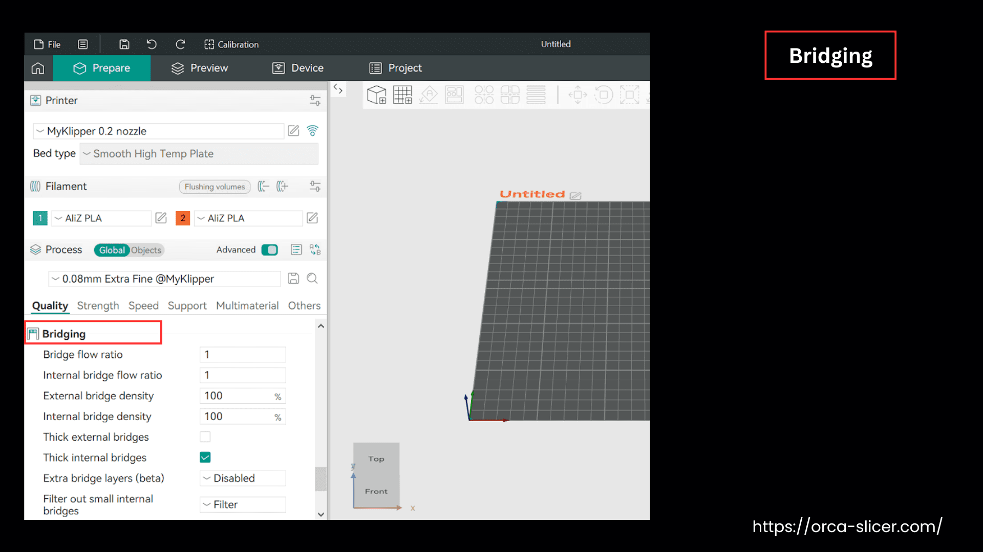
Bridging
In 3D printing, many complex structures consist of bridges. These bridges are actually the horizontal spans printed over gaps, voids, or open spaces, which you print without any support.
Bridges require special techniques during the printing process because there are no supports underneath while you print them. It means you need to print such structures with precision and accuracy, yet without any physical support. In Orca Slicer, “Bridging” settings help you print such structures without any compromise on the quality and integrity of the structure.
During bridging, the printer extrudes the filament in the air, which relies on tension and the cooling rate of the filament, unless it connects to the other side and solidifies.
In Orca Slicer, bridging settings can keep the bridge straight with the optimization of the top layer and its appearance, and avoid any sagging.
Let’s understand each setting, its impact, and its values that command a printer to print high-quality bridges.
Flow Ratio
The flow ratio controls the amount of filament coming out of the extruder during printing. If your filament is sagging, decrease this value and control the material coming out of the extruder.
Keeping the filament flow ratio low (let’s suppose 0.9) helps you optimize the actual bridge flow ratio, which is calculated by multiplying the filament flow ratio (and your object’s flow ratio if you have set it) by the value you choose here.
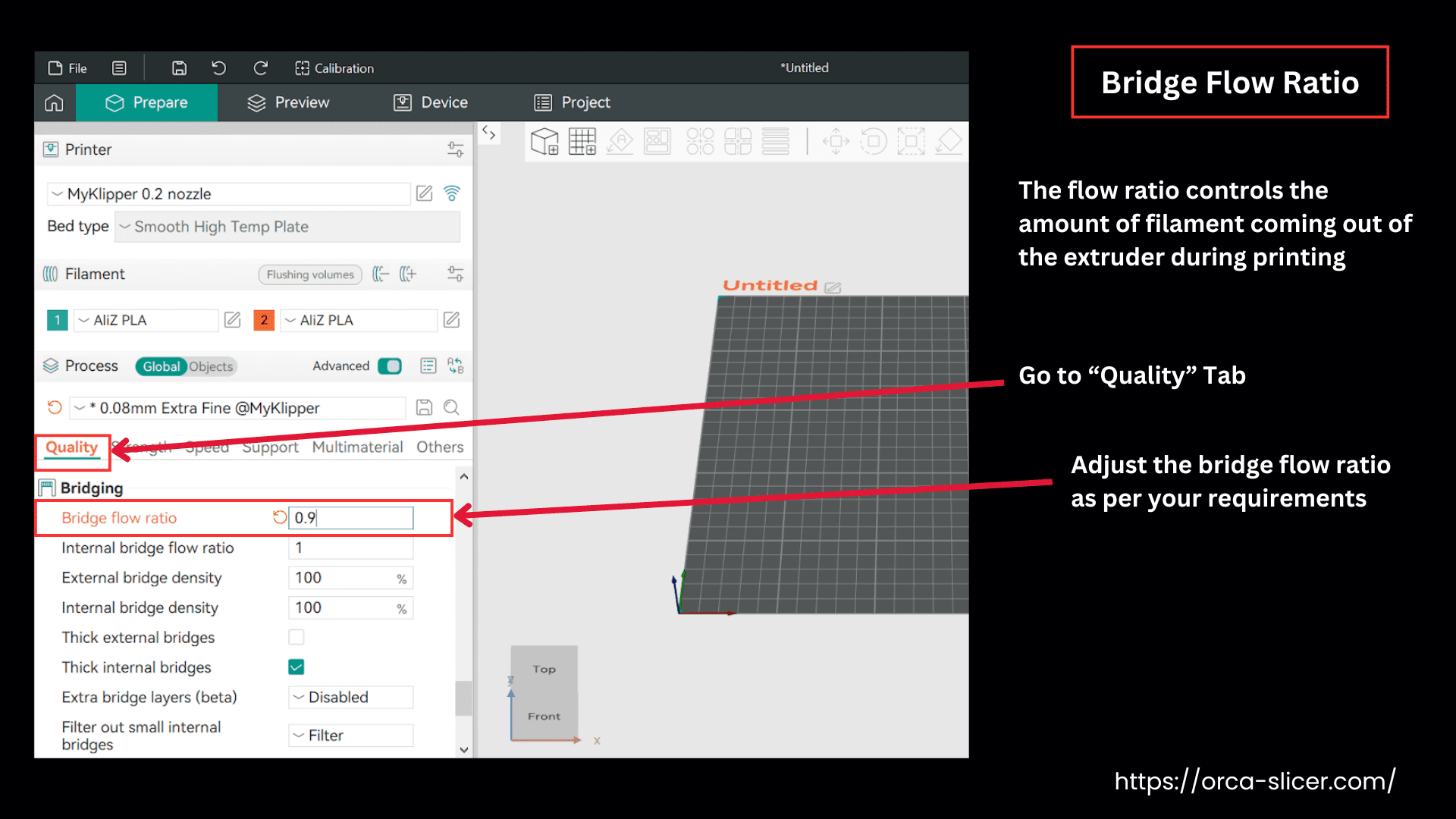
This setting commands the printer to extrude less material, which keeps your filament straight and tight in the bridge, across the gap.
Bridge Density
Bridge density defines the thickness of the bridge layer that the printer prints over the sparse infill (the base structure of the model). These settings control how thick your bridge will be printed. Controlling the thickness/density of the first bridge layer helps you set the density of the whole bridge.
Now, if your bridge layer is too thick, rough, or uneven, it indicates that the printer is over-extruding the material. Decreasing this value will reduce the amount of extruded material to an extent, resulting in a smoother surface on the bridge.
Practically, the actual “Internal Bridge Flow ” used for the bridge layer is the calculation made by multiplying this value by the bridge flow ratio, the filament flow ratio, and the object’s flow ratio (if you have set it).
External Bridge Density
This setting controls the density or the spacing between the external bridge lines. The default value is 100% which means there’s no spacing in between the lines, and it is solid. However, keeping this value a bit low adds some spacing between two bridge lines, helping in good air circulation, resulting in faster cooling rates.
Internal Bridge Density
The internal bridge density defines the spacing between the internal bridge lines. A default value of 100% usually shows that there’s no spacing between the bridge lines.
Lower values introduce some spacing between the internal bridge lines, which helps air circulation, faster cooling, and reliable solidification of the internal bridge, resulting in less swelling of the top surface. This is helpful when you choose internal bridge structures instead of the infill option.
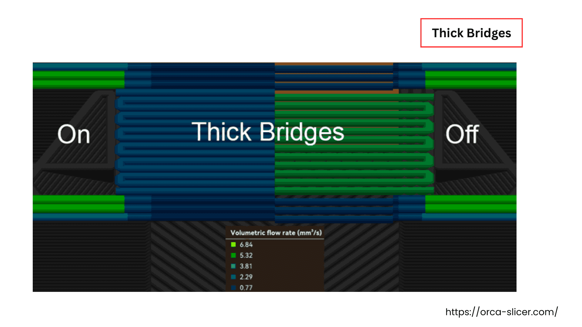
Thick Bridges
Thick External Bridges
Enabling this option/setting makes your external bridges dense and thicker, resulting in a rough surface but having more reliability and strength. You can enable this for longer bridges, as they result in stronger and reliable bridging. Disabling this setting makes the bridges visually smoother and appealing, but it is only suitable for short-distance bridges.
Thick Internal Bridges
When you enable this setting, your internal bridges are thicker, giving a more reliable structure. Enabling this setting is usually recommended, but for larger nozzle diameters, it is kept “Disabled”.
Extra Bridge Layers
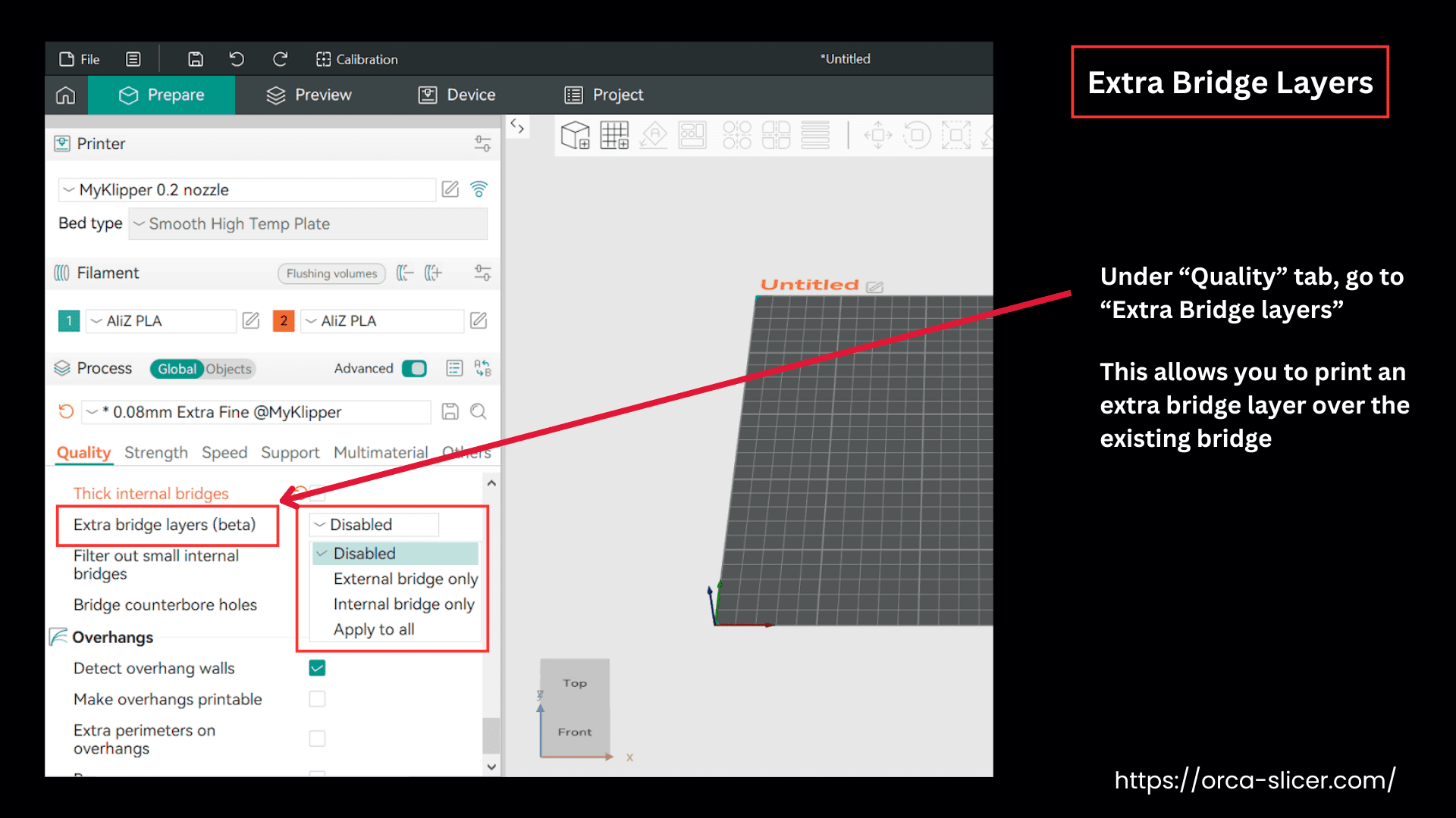
Extra bridge layers is the setting that offers a few more options, allowing you to print an extra bridge layer over the existing bridge. You can further modify the appearance and quality of your bridge by printing another top layer on it. It helps to have an improved surface finish, resulting in higher print quality, reliability, and visual aesthetic of the bridge.
It is essential to understand that the first bridge is printed on a space or gap. When this setting is enabled, your bridge is further supported by a fine-quality top layer, enhancing the overall solid infill support.
This setting is helpful in fast printers, as the printing speed of bridging is different from the infill speed.
Enable the external bridge only. You can choose other options when you need other bridge layers or your print model has specific requirements.
Now, let’s understand what each option under “Extra Bridge Layer Setting” means.
Options:
Disabled: Choose this option if printing an extra layer isn’t compatible with the 3D model’s requirements. Enabling “Disabled” does not generate any extra bridge layer.
External Bridge Only: When you enable the “external bridge only” option, your printer only prints the extra layer on the visible bridge sides or the external facing bridges.
In this setting, the bridges that are too small or too thin (smaller than the number of wall lines you’ve set) are automatically skipped, because adding another bridge layer there will not make any real improvement.
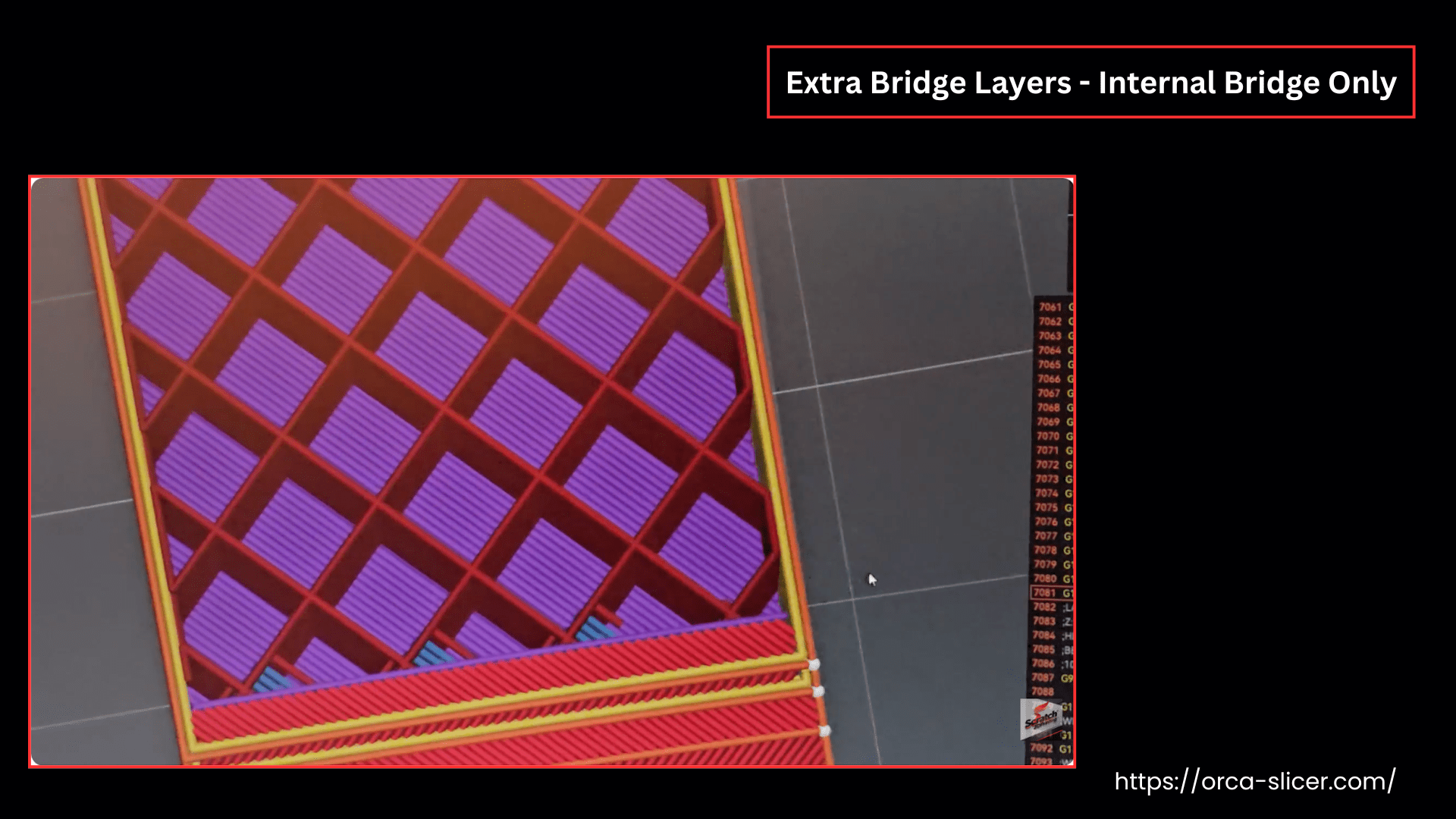
Internal Bridge Only: This option in the Orca Slicer enables the printer to print the second bridge layer on the internal bridges only, which are already printed on Sparse infills.
As the internal bridge layers are part of the top layer shell, the number of these layers is counted in the total number of the top layer, which you have set for your bridge.
The second internal bridge layer is printed nearly at a right angle to the first bridge layer, printing a criss-cross pattern of internal bridges, enhancing the overall strength of the bridge.
Sometimes a 3D model has an area with bridges in different directions (called an “island”), Orca Slicer will use the angle of the last region in that island to decide the direction for the second bridge layer.
Apply to All: This option enables the printer to print second bridge layers for both internal and external bridges.
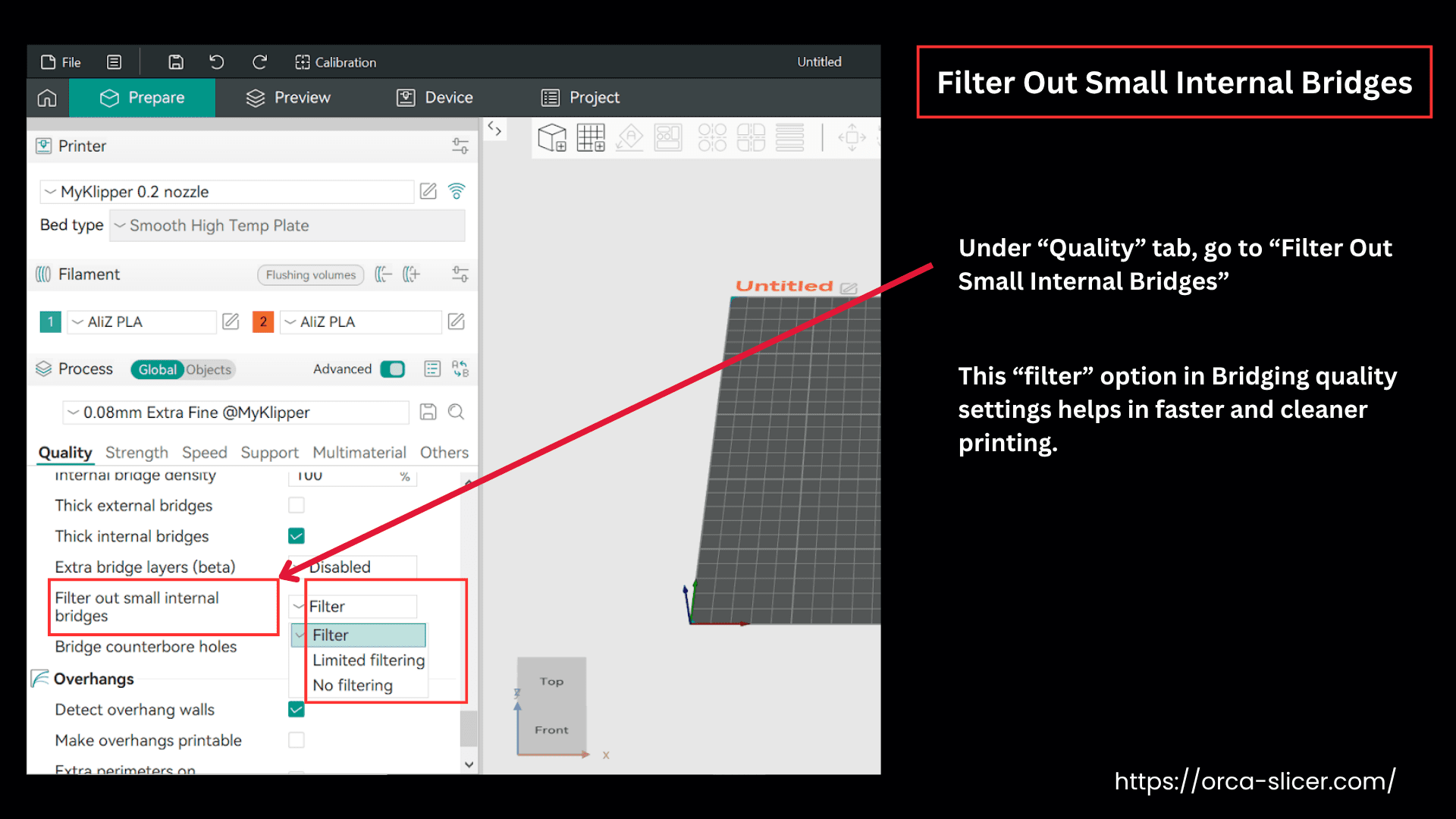
Filter Out Small Internal Bridges
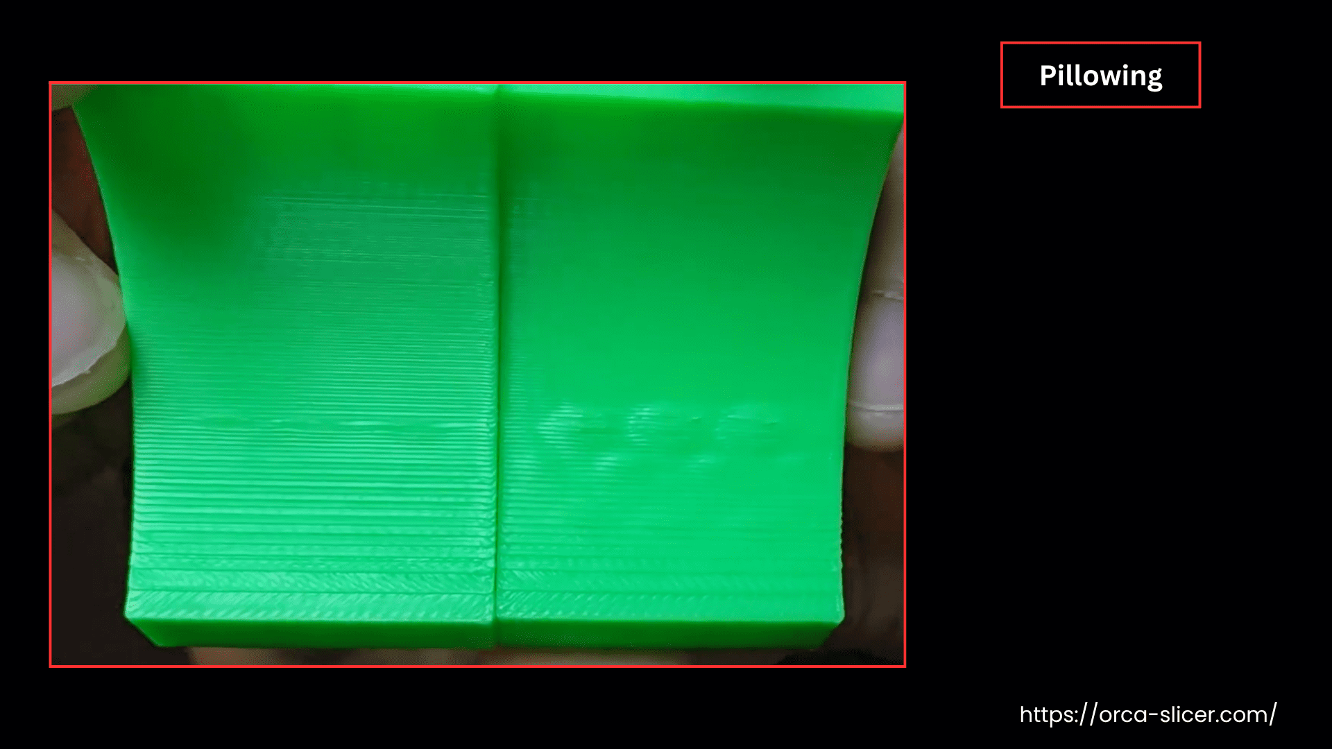
Sometimes, under a solid curved or slanted top layer, many internal bridges make the surface uneven and swollen, known as pillowing.
By default, Orca Slicer ignores these internal bridges by filtration and only prints the solid infill at the top layer over sparse infill. This “filter” option in Bridging quality settings helps in faster and cleaner printing.
This filtration works great in solid infills with higher sparse infill density models, but in heavily slanted models, it works differently.
When a 3D model is heavily slanted or curved with low, sparse infill density, the top surface goes through curling of the unsupported infills known as pillowing.
The internal bridging is shown in the image where the “no filtering” option is chosen and the object is curved.
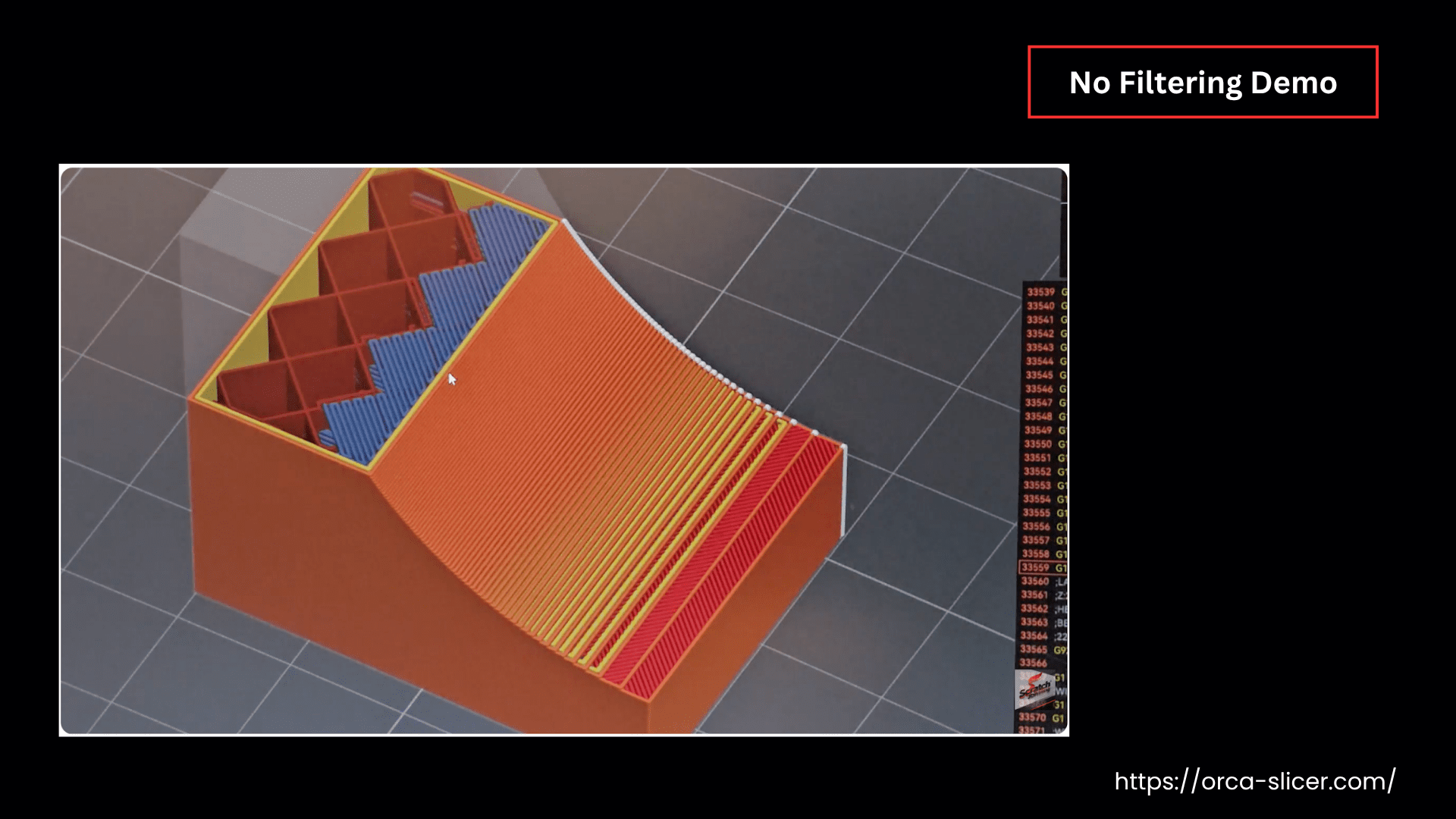
In the following picture, you can see that the first part is printed well, whereas the second part shows surface non-uniformities known as pillowing.
So, if you turn on “limited filtering” or “no filtering”, OrcaSlicer commands the printer to print controlled internal bridges in the areas of unsupported internal solid infills.
By choosing “Filter” options, you can control the sensitivity of these internal bridges, giving extra support and still keeping the surface finish at its maximum quality.
Here are the three options in the “Filter Out Small Internal Bridges” setting, which control the behavior and the sensitivity of the internal bridges.
- Filter: is the default option that filters out all the internal bridges. This option works fine in most of the 3D printing scenarios.
- Limited Filtering: enables internal bridge printing in limited areas where the model is curved or heavily slanted and needs the support of the internal bridges. Still, this option controls the formation of unnecessary internal bridges and is used for the most difficult models.
- No Filtering: is used where the 3D model is so heavily slanted, specialty at the top surface, that you can’t avoid any internal bridges in it. But this option also creates so many bridges, makes the printing slow, and uses more material.
So, in simple words, the difference between these modes is how strict the slicer is in deciding when to add or skip these small internal bridges.
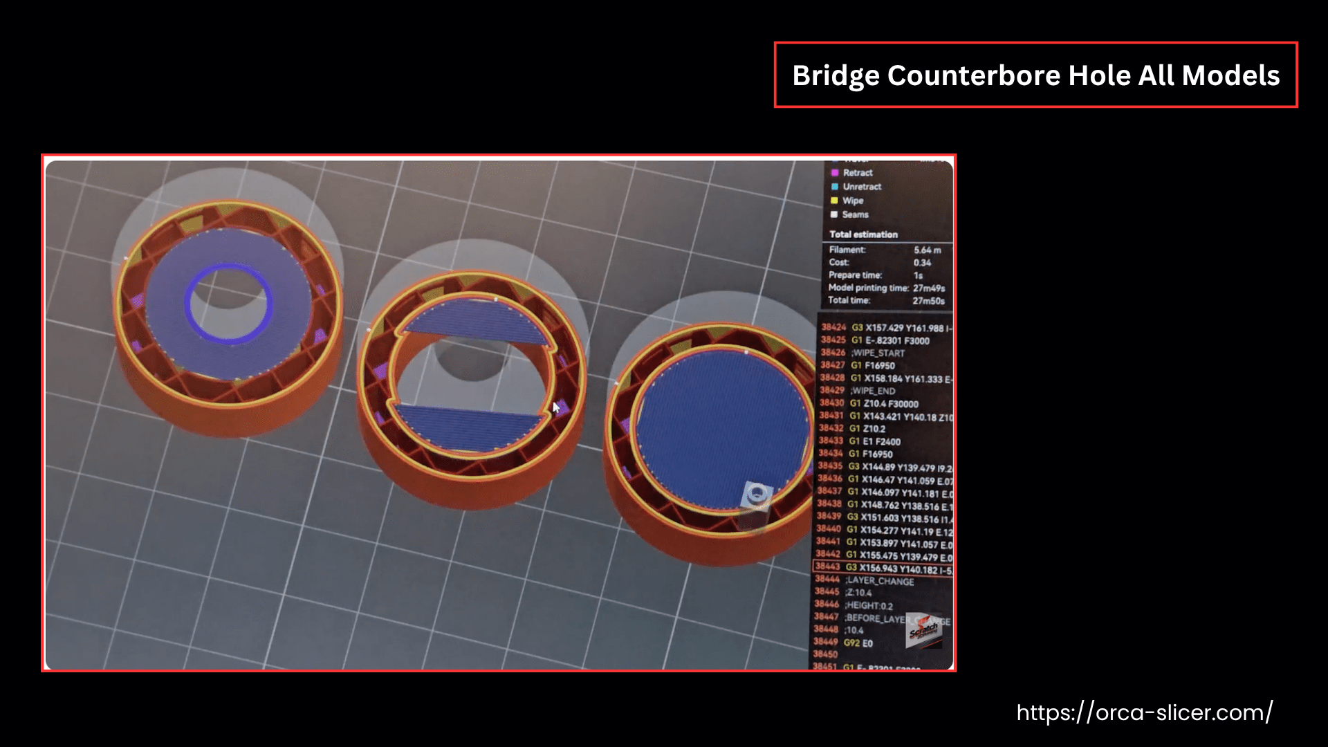
Bridge Counterbore Hole
If no support structures or overhangs are used for counterbore hole printing in the Orca Slicer, which leads to surface deformities. The 3D object with a counterbore hole may have sagging, gaps, or miss-outs of the perimeters during printing.
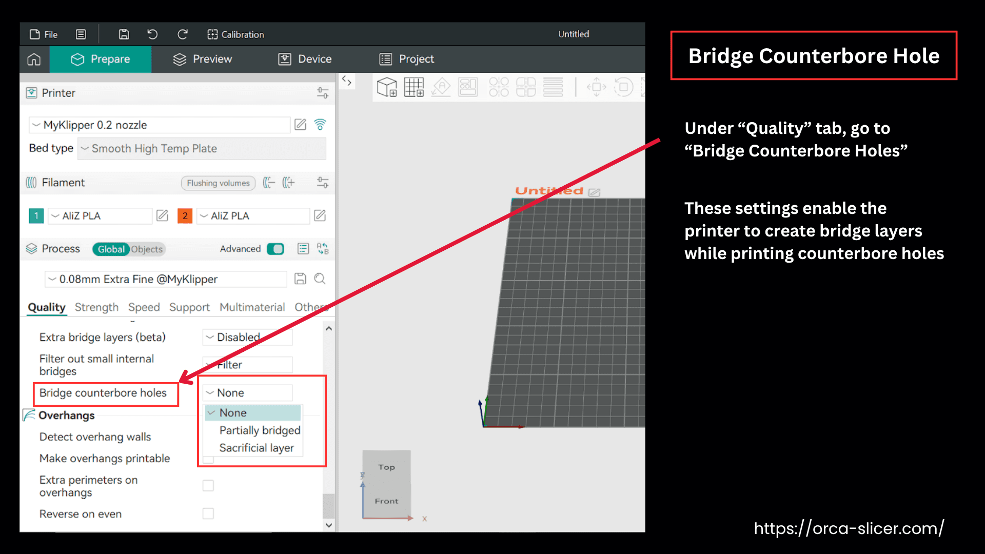
In the latest version of Orca Slicer, the “Bridge Counterbore Hole” setting has been introduced under the “Bridge” category within the “Quality” settings section.
These settings enable the printer to create bridge layers while printing counterbore holes. The temporary bridge layers can be removed after printing, allowing you to achieve high-quality holes without the need for supports or overhangs.
Bridge counterbore holes setting has these three options/models:
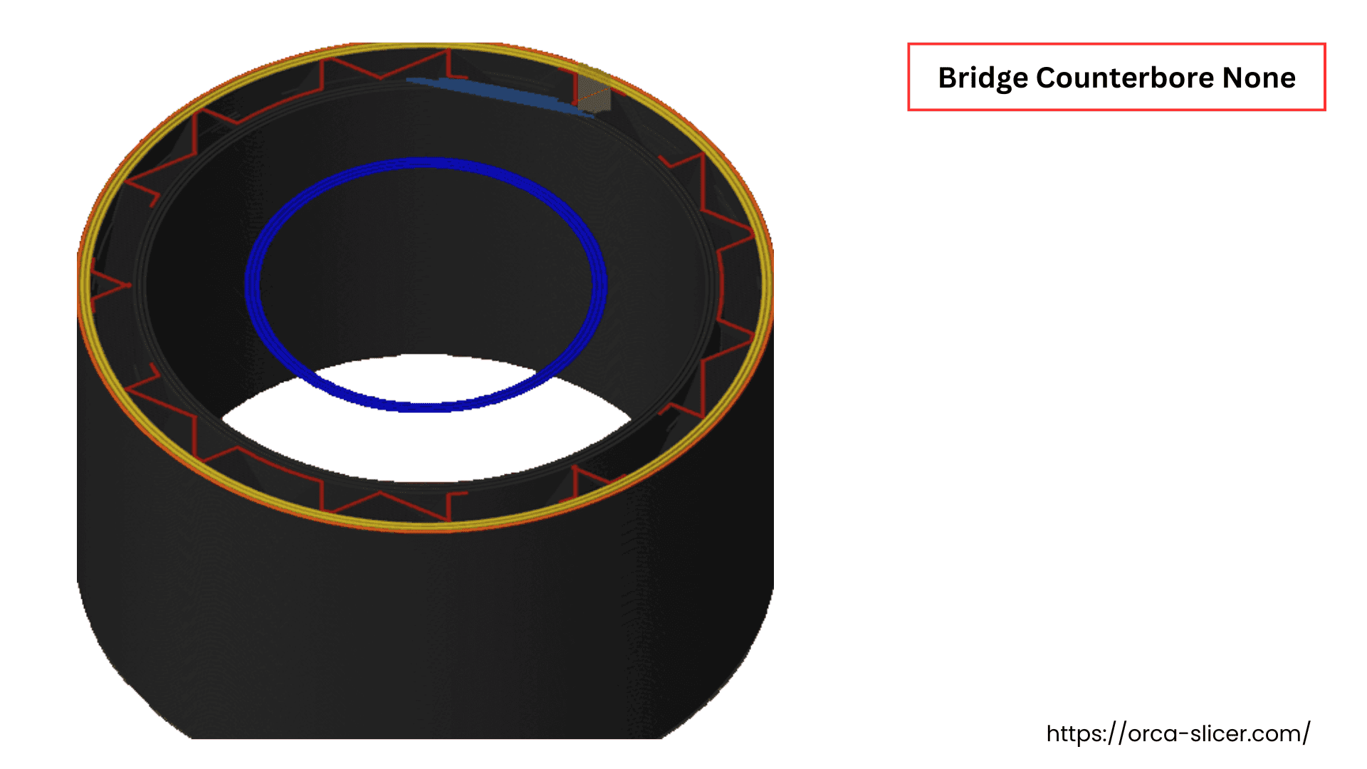
- None: prints a counterbore hole without any bridge. This setting is not recommended as it gives surface imperfections.
- Partially Bridged: enables partial bridges printing on both sides of the hole and gives some partial support to print the next layer or the perimeter of the counterbore hole.
- Sacrificial Layer: setting prints a full-fledged sacrificial layer of the bridge, which supports the counterbore hole layers to be printed on it.
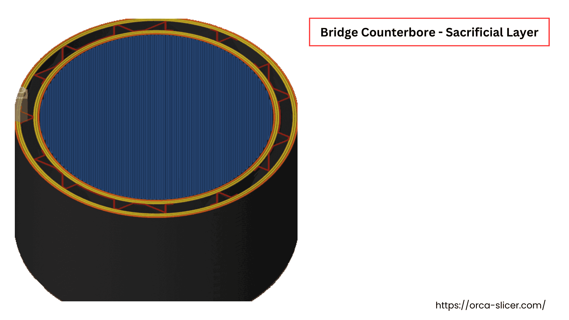
In the following picture, three counterbore hole models are shown with “None”, “Partially Bridged”, and “Sacrificial” printing settings.
Always remember this bridge layer is printed for support purposes and should be removed or broken through after printing.